The Shunt or Self-excited System
The shunt method features a simple design to provide input power to the AVR. This method requires no additional components or wiring. When problems arise, troubleshooting is simplified with less components and wiring to check.
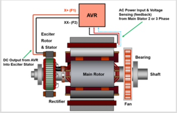
As the generator is rotated, the stator supplies input voltage to the AVR. In addition, the AVR has sensors that monitor the output of the stator.
The AVR supplies DC power to the exciter fields and This produces AC at the rotation exciter, this AC power is rectified to DC current by the rotating diodes (Rectifier) The DC current then sent to the Main Rotor and is induced onto the stator for load output as AC power.
The biggest drawback to this system is that the AVR is impacted by the load the generator is powering. When the load increases the voltage begins to decrease and the AVR must provide more current to the exciter to support the demand. This pushes the AVR to its limits. If the AVR is pushed beyond its limits the excitation field collapses. The output voltage is reduced to a small amount.
If a short circuit occurs in the supply to the AVR, the generator will not have an excitation source. This causes a loss of generator power output.
Generators with shunt or self-excited methods can be used on linear loads (constant load). Applications that have non-linear loads (varying load) are not recommend for generators with this excitation method. Harmonics associated with non-linear loads can cause excitation field breakdowns.
Recommended Metering and Testing Instruments
- Good quality Multi Meter
- Frequency or HZ meter
- Clamp Meter
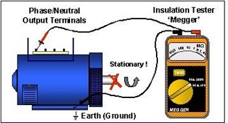
- Megger
- 24VAC variable voltage power supply
- Low resistance Meter
DO NOT attempt to work on live equipment if you are not qualified or experienced in this work
Testing Live Equipment

- Set up for test
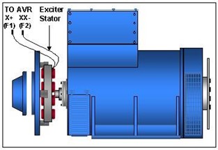
- Disconnect the Exciter Stator leads positive and negative, from the Automatic Voltage Regulator (AVR).
- These terminals are marked X+ (F1), and XX- (F2), respectively.
-

- Ensure that the correct two exciter leads are identified, by physically tracing them back to the exciter stator windings, fitted inside the non-drive end bracket of the Generator.
- Check the Exciter Stator Resistance
- Check the resistance value of the exciter stator across these two leads (approximately 18-30 ohms) with a Multimeter. Refer to Operation and Maintenance manual for correct values.
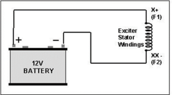
- Battery Test
- Connect the D.C. battery supply to the exciter stator leads, positive to X+ or orange (F1), negative to XX- or black (F2).
-

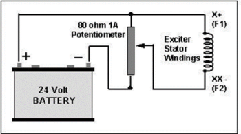
- A variable source can be applied to the circuit, as shown: –
-

- Run the Generator at Nominal (normal) Speed.
- 4 pole alternator 50Hz is 1500 rpm
- Ensure that the speed is within 4% of the nominal. The engine speed must be correct, to avoid misleading test results.
- Excitation Voltage at No Load.
- It is essential that ALL LOAD is disconnected from the machine, and that the speed is correct.
- Check the Battery Voltage after connecting to the Exciter Stator, a minimum of 12 VDC is required.
- When testing with a fixed battery supply, any difference between the figures below, and the actual battery voltage, will affect the test results, and should be taken into account. For example, if your battery voltage is 10% higher or lower than the figures shown, you can expect the Generator voltage to be equally 10% higher or lower than expected. The following chart gives the approximate D.C. battery voltages required to produce nominal output voltage ± 10% from the Generator at no load.
-

- Checking the Generator Output Voltage
- Using a Multimeter, or accurate panel Voltmeter, test the output voltage across the main terminals, Phase to Phase, and Phase to Neutral.

If the output voltage from the main stator is within 10% of the nominal, or higher than the nominal, and is also balanced across the phases within 1%., this indicates that the main stator, the main rotor, exciter stator, exciter rotor, and main rectifier diodes, are all functioning correctly.
Proceed directly to Test Number 13.
- If the output is unbalanced phase to phase, or more than 10% below the nominal, this indicates that a fault exists in one of the above components, and the following tests must be conducted,
- Checking the Main Stator Winding
- The voltages between phases, and each phase to neutral, should be balanced, to within 1% of the nominal voltage.On a single-phase machine the voltage between L1-L4, and L2- L4 or U-N and W-N, must be balanced. If the voltage is 10% or more below the nominal voltage, but is balanced within 1% phase to phase, the Main Stator is good.
- Proceed to test number 8.
- If the ph–ph voltage is unbalanced by more than 1%, this indicates that the main stator windings are faulty.This test should be repeated with all external connections removed from the Generator terminals, to eliminate the possibility of external shorts in the output cables, or the circuit breaker Further tests may be made on the resistance values of the main stator windings with a Kelvin Bridge resistance test meter.(refer to the Operation and Maintenance manual for main stator winding resistance values).
-

- Rectifier Components
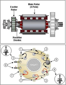
- A.C Connection Stud
- 2. Rectifier Plates
- Diodes – 3 X Negative
- Diodes – 3 X Positive
- Surge Suppressor (Varistor)
- Main Rotor Leads
- Rectifier Hub
- Symptoms of a Main Stator Fault
- A fault in the main stator windings will produce short circuit currents between turns in the main stator coil windings.When separately exciting with a battery, the current will also create heat in the damaged winding, which may also be heard as a slight loading of the engine.The three fault symptoms: Unbalanced Voltages. 2. Heat and/or a burning smell from the windings. 3. Engine sounds loaded, are all indications of a faulty main stator winding.A faulty stator winding must be repaired or replaced.
- Voltage is Balanced but reading Low
- If the output voltage is more than 10% below the nominal voltage, but is balanced within 1% Phase to Phase, (and Phase to Neutral), the main stator is good, but there is a fault elsewhere in the Excitation system.This indicates that a fault exists in the main rotating rectifier assembly, (diodes and/or Varistor), or, one of the excitation windings, (either main rotor, exciter stator, or exciter rotor).First check that the D.C. battery supply is not lower than the figures given in Paragraph 5, and that the engine speed is correct. Note: A flat battery, and/or low engine speed will give misleading test results.
- Testing the Rotating Rectifier Assembly
- The diodes on the main rectifier assembly can be checked with a multimeter. The flexible leads connected to each diode should be disconnected at the terminal end, and the forward and reverse resistance checked. (See section 2, diode testing).The rectifier assembly is split into two plates, positive and negative, and the main rotor is connected across these plates. Each plate carries 3 diodes, the negative plate carries the negative based diodes, and the positive plate carries the positive based diodes. Care must be taken to ensure that three identical polarity diodes are fitted to each plate. When fitting the diodes to the plates they must be tight enough to ensure a good mechanical and electrical contact but should not be over tightened. The recommended torque tightening is 4.06 to 4.74 Nm, (14 to 17 kg/cm).
- Testing the Surge Suppressor (Varistor)
- The Surge Suppressor (Varistor) is a protection device, which prevents high voltage transients from damaging the main rectifier diodes.High Voltage transients are created by fault conditions in the distribution system. The transient returns to the Generator via the output terminals, enters the main stator windings, and by mutual inductance, (transformer reaction), is transferred to the main rotor windings, and then the main rectifier assembly.The Surge Suppressor can be tested with a Multimeter on the megohms range.A good Surge Suppressor should have a very high resistance, (more than 100 megohms in either direction)A faulty Surge Suppressor will be either open circuit (usually showing signs of damage) or short circuit in both directions.The Main Rectifier will still work normally with this device removed. However, it should be replaced as soon as possible, to avoid diode failure in the event of further transient fault conditions. Occasionally, a very high transient will totally destroy the Surge Suppressor. This could result from extreme fault conditions, such as lightening, (electric storms), striking close to overhead distribution lines, or out of phase synchronisation of the Generator, when paralleled to multiple Generator systems, or embedded systems connected to the Mains, (Grid, Utility) supply. In the event of a Surge Suppressor failure, all rectifier diodes should also be replaced, including any which appear to test OK.
- Testing the Excitation Windings
- After establishing and correcting any fault on the rectifier assembly, the battery test should be repeated, from paragraph 6, and the output voltage checked. If the output voltage is still more than 10% below the nominal voltage when separately excited, this indicates that the fault must be in one of the excitation windings. To test the main rotor, exciter stator and exciter rotor winding, the resistance values must be checked against correct values, which are given in the Operation and Maintenance handbook, supplied with the generator. Refer to the Service and Maintenance section, for the winding resistance charts, specific to each Generator type and size. Note. The charts require identification of the frame size, number of rotor poles, followed by the main stator and rotor core length (A, B, C–G, H, J etc). The Main Stator core length and winding number are given on the Generator nameplate.
If in doubt, refer to the factory, with the Generator serial number or machine identification number.
- Exciter Stator
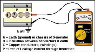
- The exciter stator resistance is measured across leads X+ and XX- (F1 and F2), which should be disconnected from the Automatic Voltage Regulator (AVR), terminals.A standard Multimeter, set on the lowest resistance range, will be suitable for this test. The exciter Stator winding Insulation to earth should also be tested with a ‘Megger’. As a low insulation can affect the AVR performance. Minimum value to earth 1 megaohm. (See section 2 for details)
- Exciter Rotor
- The exciter rotor is connected to the 6 X AC connection studs on the Main Rectifier assembly. Disconnect the 6 leads from the AC connection studs, and check the resistance value across three of the leads, which were connected to the same polarity diodes, (fitted to the samrectifier plate). The resistance value is very low, and requires a Kelvin Bridge test meter for accurate results.Alternatively, a visual inspection will usually identify any burnt or damaged windings.
- Main Rotor
- The main Rotor leads are connected to the main rectifier plates. Disconnect one of the leads to check the resistance value.A good quality Multimeter will measure resistances of 0.5 to 2 ohms with reasonable accuracy, however if the resistance is found to be lower than the quoted figure, it should be verified with a more accurate measurement.
We hope that this has assisted you, please contact us if you need some help.